EFGH Range
The On-Load Tap Changing Gear Range EFGH are designed for use with three-phase transformer operating with their neutral point solidly earthed. They are used on systems where the neutral is insulated if the working and test voltages are kept within certain voltage ratings.
Principal of Operation
The diverter switches are positive quick-acting changeover switches, using resistances for bridging between running positions during a tap change. read more....
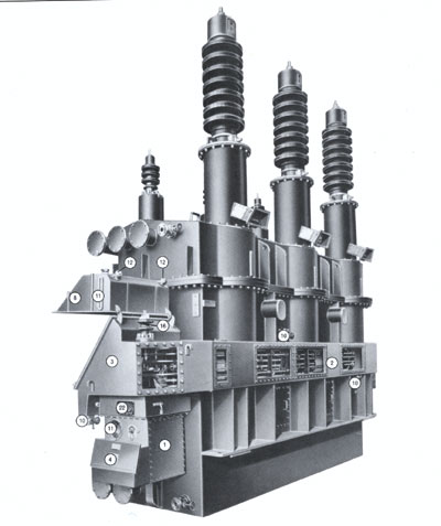
Description of Gear
The Ferranti Tapchangers Limited On Load Tap Changing Gear Type FC4, FC6, GC6, GC12, HR6, HR12, HD12 and HD14 comprise, in effect, three separate compartment parts, viz., tapping selector switches, diverter (divertor) switches and driving gear and associated control mechanism
All these component parts are mounted separately in oil filled and isolated compartments on the side of the main transformer tank, and the selector switch compartment is separated from the main transformer tank by three oil-tight insulating panels, i.e. bath tub type barrier boards, which carry the terminals for the tapping connections from each phase of the transformer windings. The diverter switch compartment is provided with a hinged bolted cover which allows easy access to the divertor switches for inspection after draining off the oil.
Operating Mechanism
The motor drive and timing gear are housed together in a compartment situated at the end of the tapping selector switch compartment.
The motor is of single-three phase capacitor start and run type and is coupled to the main tapping selector switch and diverter switch operating shaft through reduction spur gearing.
At one end of the main driving shaft is a spur gear which operates a Geneva wheel mechanism and in turn drives the selector switch lead screws. The Geneva wheel mechanism incorporates an arrangement giving 180deg lost motion on reversal, which provides the correct selector switch sequence. The use of a Geneva wheel mechanism ensures that the tapping selector switches are only moved one step at a time and that they are locked in position except during the actual period of rotation.
A crankshaft is fitted to the other end of the main driving shaft which, through a connecting rod, gives a reciprocating motion to the diverter switch operating lever. This lever, through springs drives a toggle mechanism which operates the assembly carrying the moving diverter switch contacts.
The control or timing gear is mounted in a compartment adjacent to the motor and reduction gear train, and includes all the equipment required for control of the tap change gear, with the exception of remote indicators and control switches, which reduces the number of leads between the transformer and the control point to a minimum.
A camshaft driven from one of the gears in the reduction gear train times the whole sequence of each tap change operation, drives a local mechanical tap position indicator, a transmitting device for remote indication of tap position, and operates the electrical limit switches.
A cam operates a normally open contact which closes during a tap change, a changeover or 'sense' contact which ensures that the gear continues to operate in the appropriate direction, and a normally closed contact which opens during a tap change.
Motor Gearbox and Timing Gear
The driving motor, gearing and timing gear are all contained in the lower half of the gearbox. All these items are immersed in oil to ensure constant lubrication of the motor, gearing etc., to give long trouble free operation. It also reduces the number of oil seals, only one oil seal being required between the gearbox and the diverter switches, and one oil seal between the diverter and selector switch compartments.
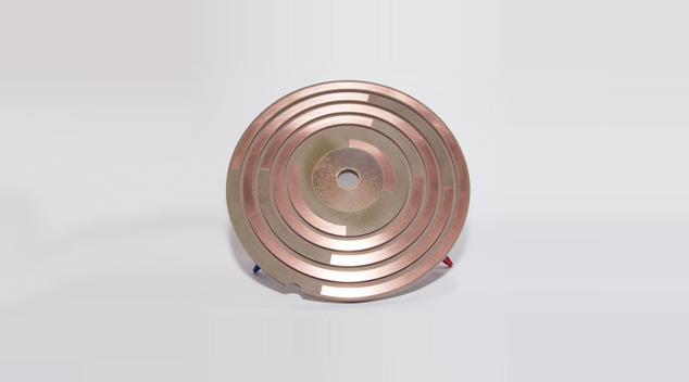
Selector Switches
As previously mentioned the selector switches are mounted in a separate compartment built on the side of the main transformer tank. They are completely isolated from the diverter switches, and as they break no current, cannot be contaminated by carburized oil. Draining and filling valves are provided, and should the need for inspection arise, it is only necessary to drain the oil from the tapping selector switch compartment.
The switch contacts are of the 'in line' variety having a double row of contacts. The fixed contacts are mounted in three insulated bath tub style barrier board panel mouldings, one for each phase, which combine the functions of switch base and barrier board panels. Each insulated barrier board panel is mounted adjacent to the winding from which the tapping connections are made, thus avoiding the necessity for unduly long leads.
The hot metal pressed catapult shaped moving contact assemblies are driven by lead screws which have moulded insulated couplings between phases. The contacts are self-aligning and arranged for line contact under ample pressure. Connections from the moving contact are trunked by busbars to oil tight insulators in the end of the tapping selector switch compartment.
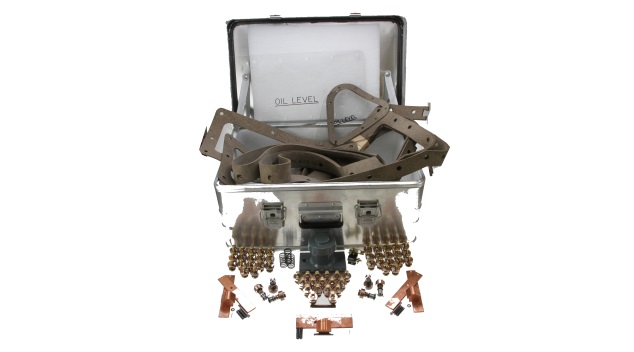
Shown here are just some of the manuals and parts available.
If you can not see the product you require, or for more information click on the Contact link above